Machine cutting capacity ability
|
Item |
Model |
Torch cable length |
Current |
Duty cycle |
Pierce thickness |
Production cutting thickness |
edge cutting thickness |
|
1-5134-3 |
CNCAM HP100 |
10m |
100A |
100% |
22mm |
20mm |
35 |
|
|
CNCAM HP100 |
15m |
100A |
100% |
22mm |
20mm |
35 |
|
1-5134-3 |
CNCAM HP100 |
10m |
100A |
100% |
22mm |
20mm |
35 |
|
1-5136-3 |
CNCAM HP100 |
15m |
100A |
100% |
22mm |
20mm |
35mm |
|
|
Solar wind HP120 |
|
|
|
|
|
|
|
1-1134-3 |
Solar wind HP160 |
10m |
160A |
100% |
30mm |
25mm |
50mm |
|
1-1136-3 |
Solar wind HP160 |
15m |
160A |
100% |
30mm |
25mm |
50mm |
|
1-1334-3 |
Solar wind HP200 |
10m |
200A |
100% |
32 |
30mm |
60 |
|
1-1334-3 |
Solar wind HP200 |
15m |
200A |
100% |
32 |
30mm |
60 |
|
1-1334-3 |
Solar wind HP260 |
Control table |
260A |
100% |
38mm |
32mm |
70mm |
|
1-1336-3 |
Solar wind HP300 |
Control table |
320A |
100% |
38mm |
32mm |
70mm |
Warning
These operation instruction is prepared for experienced operator. you should be familiar with arc welding and cutting equipment’s operation.
Please not let non-training workers installation. Operate. Maintenance this equipment.
If you can not understand this instructions, please contact your supplier for more information.
Before installation and operation this machine, please make sure read above safety and notes.
User’s Responsibility
Only according to manual instruction to install. operate and maintenance. The equipment can achieve this manual and attached labels’ described performance. The equipment regular inspection must be conducted; When there is failure or poorly maintained equipment should not be used. If components have any damage, loss, abrasion, deformation or pollution, Should be replaced immediately. Please contact by telephone or written distributors to confirm whether there is need of repair or replacement parts.
Without manufacturer's prior written approval, Please don't do STH without authorization to change the equipment or any part. The equipment’s user should take full responsibility of improper use, improper maintenance, damage, improper maintenance, or by non-manufacturer or other pointed serve organization’s refit to cause any faults.
Before install and operate, please make sure to read and understand this manual, To protect themselves and others.
Product Description
Introduction
Hai bo plasma generator is designed for high-speed plasma cutting etc. applications, can be used together with other companies’ equipments together.
·cutting electricity range can be adjusted
·forced-air cooling
·solid state DC power
·The input voltage protection
·Touch screen control
·to main transformer and High power semiconductor components’ protection
·top lifting lug or base forklift space for shipping
General specification
|
HP/100/160/200/260 380V/400V/ 50/60HZ |
||
|
Output (100% duty cycle continuous rate ) |
Voltage |
DC200V |
|
Input |
DC electricity range(cutting) |
15A~260A |
|
Power |
2-72KW |
|
|
* (OCV) |
DC360V |
|
|
voltage(3 phase) |
380 / 400伏 380 / 400V |
|
|
Frequency |
50/60HZ |
|
|
KVA |
91.6 KVA |
|
|
Power |
82.5KW |
|
|
Power factor |
90.0 % |
|
Size and weight
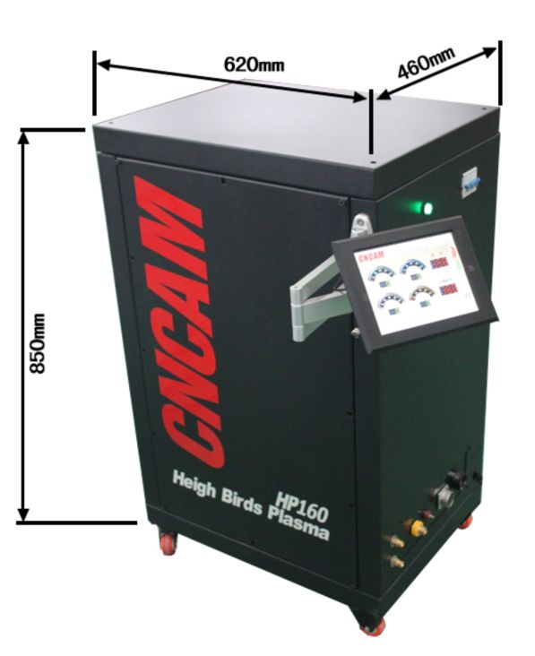
weight=82kg
Installation
Open box
3.1 Open box
● When machine is arrival please check immediately whether has damage or not.
● All components taken out from container and check container has scattered parts or not.
● Examine shutters whether has airflow obstruction or not.
3.2 Storage
● Front and back at least 1 meter (3 feet) clearance for cooling air flow.
● To remove the roof and side panel to maintenance .clean and examine to make plan.
● The location of the HP power should be relatively close to the power source with appropriate fuse
● Keep under power there is nothing for cold air flowing.
● For Environment, there is no dust. smoke and overheating. These causes will affect cooling efficiency.
3.3 Power connection
Warning
Get an electric shock to the deadly!
Please provide the maximum electric shock protection.
Before in machine finish any connection , the wire circuit on the wall isolation switch cut off to cut power supply.
3.4.1 Main power
HP power is three phase installation. Input power must be supplied by circuit(on the wall) insulated switch ; accordance with local and state regulations contain a fuse or circuit breaker.
* The recommended input wire and circuit fuse specification
|
Under the rated load input |
|
Input guide line and earthing lead *cooper/mm2(American wire gauge ) |
Time delay fuse specification(A) |
|
v |
A |
||
|
380 |
140 |
50 (1) |
200 |
|
400 |
132 |
35 (2) |
150slowly melting+10%/-0 |
Related load 200V 360A output
*Specifications are according to American 《National Electrical Code》in 40 ℃ (104 degrees) using the rated temperature is 90 ℃(194 degrees) of copper wires.
Cable pipe or cable shall not be more than three wire inside. If local codes specified in the specifications and the above different, should follow the local codes.
To estimate a wide range of input current output criteria, please use the following formula:
|
Input electricity |
(V arc) x (I arc) x 0.73 |
|
(V circuit) |
Annotation
It may be necessary to use a special power line.
HP power line has voltage compensation ability, but in order to avoid damage due to circuit overload to damage performance. need to use special power.
3.4.2 Input guideline
· Supplied by customers
· For the copper wires with thick rubber sheath (three root power line and a ground wire) or by rigid or flexible tube wiring.
· According to the chart to determine the specifications
3.4.3 Input connection procedure
Warning
Incorrect grounding can cause personal injury
The machine frame must be connected to the approved electrical grounding line. Determine the grounding wire is not connected to any terminal
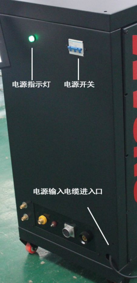
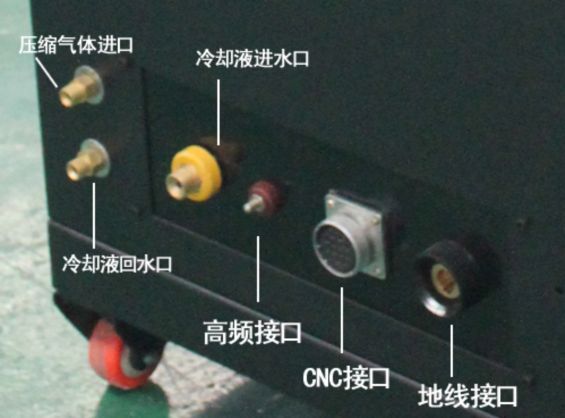
3.5 Output connection
Warning
Get an electric shock to the deadly! Dangerous voltage and current on the Removed cover plate’s plasma power supply
1. In line (the wall) isolating switch to cut off the power supply
2. Let the qualified personnel use voltmeter to detect output bus bar(the positive and negative)
3.5.1 The output cable (provided by the customer)
Based on per 400 Ann output current need a 4/0 AWG (AWG) 600 v insulated copper wire
Annotation:
Do not use 100 v isulation welding cable .
4.0 working
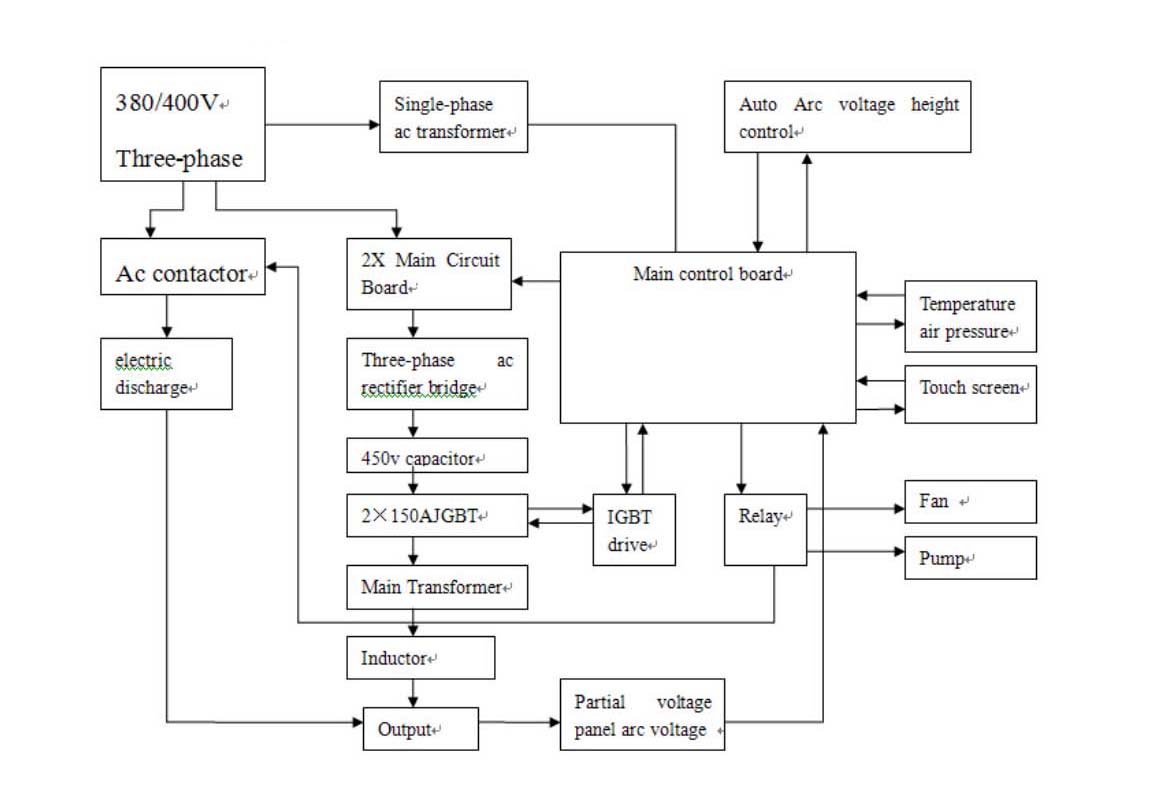
HP Power supply diagram HP
4.1.1 The control system the main menu
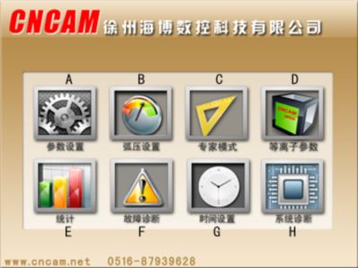
A - Parameter setting
Set arc voltage height adjustment related parameters
B - arc voltage setting
arc voltage height adjustment related parameters dynamic monitoring
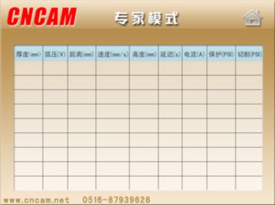
C - Specialist mode
According to the sheet thickness selecting standard parameter Settings
D - Plasma parameter
Plasma cutting related Settings
E - Statistics
F - Troubleshooting
examine the current system to detect the fault description and solution
G - time Settings
The machine clock Settings
Statistic cutting time and piercing numbers
H – IO diagnosis
examine input/output IO port function
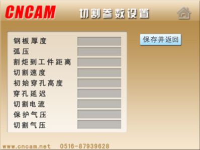
4.1.2 Parameter Settings interface
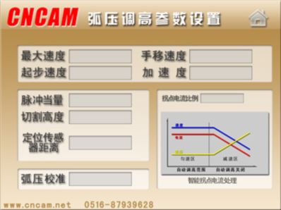
1. Max cutting speed: mm/min
According to the motor performance setting, If in sleep mode can be set up in 1000-2000 - mm/min. Plasma cutting is best set in more than 3000mm/min. 5 mm screw set up 3500-4000 - mm/min is suitable.
2. Starting speed: mm/min
General Settings at about 150-400 - mm/min.
3. Hand moving speed: mm/min
Press up and down key moving speed, generally hand moving speed is smaller , Easy to accurate positioning ,general Settings at about 800-1500
4. Accelerate speed:
Press up and down key moving speed, general hand moving speed is smaller , Easy to accurate positioning ,General Settings at about 800-1500
5. Pulse equivalent:
Refers to the mobile 1 mm need to send how many pulses, This setting and fine screw pitch and motor score with related calculation method. One revolution pulse equivalent = the number of pulses required/pitch.
6. The cutting height
Initial position’s cutting height
7. Positioning sensors distance:
Due to the sensor has a certain response distance, accurately setting Positioning distance can more accurately set cutting height.
8. Arc voltage calibration
Due to the cutting nozzles’ damage caused arc voltage and height adjust parameters not accurate,
9. Inflection point current ratio:
According to the set ratio to reduce the proportion of the inflection point of the current, Avoid burning nozzle phenomenon
4.1.3 Arc voltage Settings interface
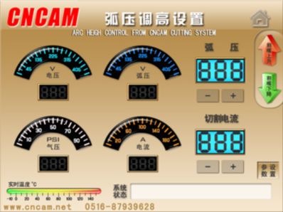
The interface separately real-time monitoring, 380 v voltage, air pressure, arc voltage, current and temperature. If there is a problem will real-time fault diagnosis analysis.
On the right side, arc voltage and cutting electricity, point data’s central position will Pop-up digital keyboard Settings, can also through ‘+’、‘-’key to adjust slightly.
Through pressing ↑、↓ to move cutting gun to up and down.
4.1.4 The plasma parameter Settings interface
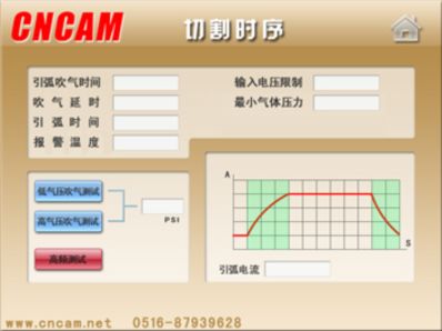
● Arc blowing time: unit MS(1s=1000ms)
To start to cut, firstly to blowing, if pipe line is too long, this parameter need to set bigger, Prevent gas cannot achieve cutting position, Unable to form plasma arc, damage to the cutting torch.
● When blowing delay
When cutting is finished, to give cutting gun, nozzles and consumables for the cooling blowing, Set this blow last time
● Arc blowing time
When high frequency arc set time. the parameter under the premise that can guarantee the successful ignition set as far as possible, This can prolong the service life of electrode cutting nozzle.
● Reported the police temperature
Plasma heat sink over setting temperature alarm, Display alarm interface
● Into the voltage limit
Main board more than setting the temperature alarm, Display alarm interface
Set below 300 might not arcing
General Settings more than 320 v, lower than this parameter will appear some fault or cutting ability is bad.
● Smallest gas pressure
Normal atmospheric pressure In 4 to 6 psi. Plasma arc starting air pressure is in commonly 10-20 psi is better, When cutting at 45 to 60 PSI, is below the set of PSI will report to alarm.
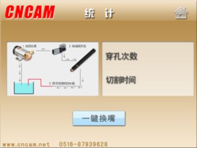
● one key to change nozzle
100 a water gun Without this function, But can press one key to change nozzle to clean piercing times and cutting time to zero.
water gun first stop working pump and electromagnetic valve to open, blow air into the cutting torch, The coolant back to tank. After the process change the cutting nozzle, Utmost to avoid the loss of coolant. At the same time, the number of perforation and cutting time to reset, one key to change nozzle is finished.
one key to change nozzle executes main transformer circuit to stop any work, prevent the operator to get an electric shock.
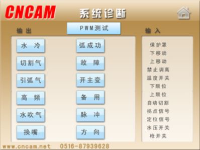
● System diagnostic
Press the output button, the corresponding output port indicator light will have on and off action, meantime, on the mainboard the corresponding indicator will also has action. Use this test port is good or bad.
If the indicator light and display are different, it declares output part has a problem
5.0 Maintenance
5.1 General
Warning
Get an electric shock can be deadly!
Before trying to conduct any maintenance work, use line (the wall) isolating switch to cut off the power supply
Warning
Use compressed air to clean has harm eyes’ danger.
1. During cleaning power should Wear approved side cover eyes protective equipment.
2. Only can use low pressure air.
Attention
The maintenance of this equipment should only be performed by trained personnel.
5.2 Clean
In order to help keep the power supply trouble-free operation, it is necessary to conduct regular cleaning. The frequency of cleaning depends on the environment and usage.
1. On the wall isolating switch to cut off the power supply
2. Take off two sides’ panel.
3. use low pressure without water Compressed air to remove all the air channel and parts’ dust. Especially need to pay attention to the power supply at the front of the radiator. Dust will be cut off and reducing heat.
Please wear eye protection equipment.
Attention
Air flow limit can lead HP-power overheating.
Hermal switch may action, and interrupt the work.
This equipment can not be used air filter.
Keep the air channel no dust and other obstacles.
Get an electric shock harm.
Before the power on, make sure install back any cover
6.0 Troubleshooting
6.1 Troubleshooting introduction
Referring to the back troubleshooting guide according to symptoms to find problems. Remedies may be quite simple. If you cannot quickly find out reasons, Cut off the input power, Open the power supply, to all components and wiring for a simple visual inspection. Check the terminal connection is firmed, Whether has loosing or burned wiring and components.
Controlling problem’s reason may be able to by reference to the operation sequence. Electrical schematic diagram and Check the relevant parts to find. Some of the check will be necessary to use v ohmmeter.
6.2 Troubleshooting guide
when the power supply is on, display should appear EP for a second, and then display program code, such as Pr 3.01 or higher. If the display is always blank,
Check whether has the following situations or not:
a. Between the main control board and display board has loose or missing cable
b. No + 15 v bias voltage, this may be caused by the fuse fusing of F1 or F2
c. On the front panel circuit breaker CB1 open.
If the power supply after the program code then shows the Error (Error. 5) 5, check whether has a closed starting switch. If you want to reset the power supply, just click on the switch to open. At this time display two Windows should be 0. If when the power supply is on but not connected to CNC, Power inner’s emergency stop relay (K4) will not has electricity, make power itself does not make any relay action.
If CNC has been started, the display of the volt and ampere reading should be 0. On the main power choosing input (J1 H needle) in 115 and has input (main power supply to choose input) before the wire connection, this unit will not respond to start signal. This connection shall be the responsibility of the cnc to the main power cable. Please note, from cnc input all relay closed, to isolation plate(within the power supply Printing plate 4)supply ac115 input. The isolation plate convert these inputs into open collector to output. This control will monitor multiple signals in idle mode, and when the conditions were not met downtime and giving wrong instructions: Error 1, 3, 4, 5, 9 or 12 (see section 6.3 "help code" list).
When the switch is enabled and cutting power in cutting preparation, Will monitor some additional conditions. The resulting error status : Error 2, 6, 8, 12, 13, 14, 15, 17, 18, 19 or 113 (see section 6.3 "help code" list).
6.3 Fault isolation
6.3.1 The fan doesn't work
|
The problem |
Possible causes |
Correct measures |
|
All three fan don't work |
This is a normal phenomenon when not cut. Fan only when received "contactor" signal will work |
without |
|
1 or 2 fan is not running |
Fan motor circuits damaged or broken wires |
Repair wire |
|
failed fan |
Replace fan |
7.0 Replacement parts
7.1 General
Please always provide the components’ (will be used) unit serial number. Serial number imprinted on the unit nameplate.
7.2 Purchase
In order to ensure the normal work, it is recommended that the equipment only use the original ESAB parts and products. Using the parts not supplied by ESAB may let maintenance invalid.
Replacement parts can be order from ESAB dealers.
When ordering replacement parts please make sure that any special delivery requirements.
If you need customer service phone number, please refer to this manual back cover’s communication guide.
|
EPP-360 power of information |
|
|
Part number |
EPP-360, CCC/CE, 380 / 400v, 50 / 60hz |
| 0558007831 | |