


(Assembly drawings)
Guide rail installation
1. Premise requirements (Prepare installation tools) as shown in figure 1
(1) Ruler
(2) Automatic installation level
(3) Support bracket
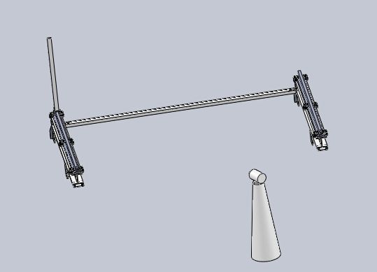
Figure 1
2.Installation instructions
(1). Need to find hard ground which can hold the whole machine.
(2).Put the separate rails correspondingly connect to (M10 Bolts)As figure2,connect both rails well.
(3).The size of guide rail center3368mm(3368/25.4=132.6〞).as figure3. This guide rail weight is 24Kg/m,rail width 40mm,center size:guide rail center to guide rail center.
(4).In order to protect both ends of rail,need to Pull the diagonal(figure 4),Ensure the dimension of the diagonal, etc.((only at one end of rail to defined a certain length for reference point,such as 4meters.)
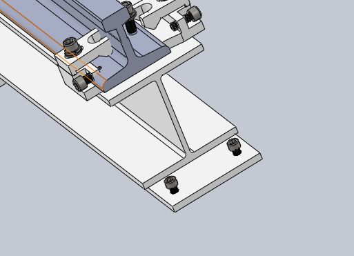
Figure 2
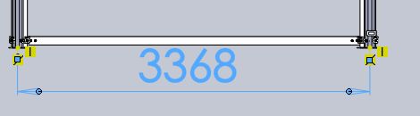
Figure 3
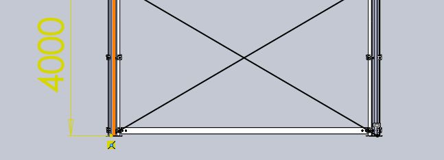
Figure 4
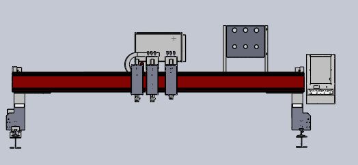
(5). Use the prepared tool as Figure5
Put the Automatic installation level and support bracket between in both sides rails(width. Length)
(a). Put the ruler on the rails(divided into several points),ensure all the points height consistently(range 0.3mm),adjust M14nut as figure6(this is rough adjustment).
(b)Use a gradienter(there are bubble inside),,to Check whether there is a high and low on both sides of the guide rail(before delivery we adjusted slightly),if still have problems, need to adjust slightly, figure7.
(6). Install connector M10as figure8.
(7). Install the anchor bolt on the ground(each support bracket),as figure9
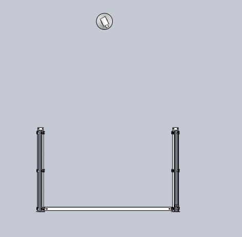
Figure 5
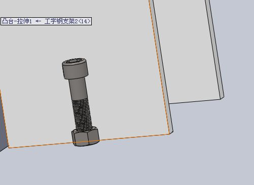
Figure 6
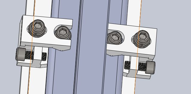
Figure 7

Figure 8
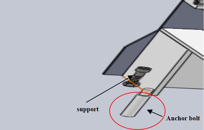
Figure 9
The guide rails have installed completely.
2.Machine head installation
1.Removed the machine casing,as Figure10
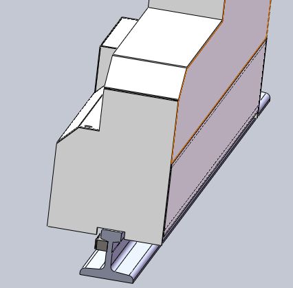
Figure 10
2.To adjust left.right bearings to the maximum
(ourside is concentric adjustable bearing,inside is eccentric bearing)as figure11.
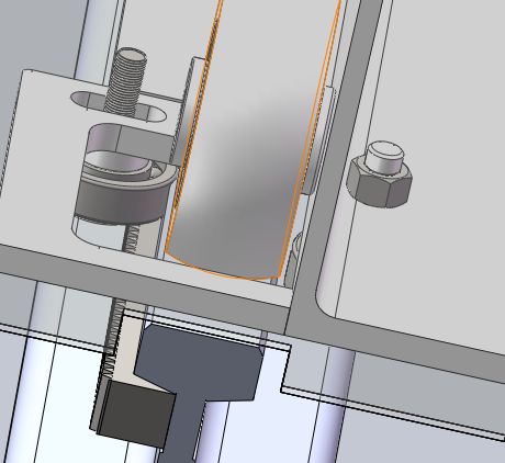
Figure 11
3. Put machine head on the installed rails,make the left and right longitudinal beam’s wheel and one side of rail(bevelled inside) alignment.
4. Put left.right both sides’ bearing can be closely contact with guide rail.
Machine head has installed completely!
3.Ground machine’s Adjustment of diagonal.
1. Install line pencil on flame cutting torch.
2. Paste four A4 papers on steel plate, the papers’s distance about two meters.
3. The moving torch draw”十”pattern on four line papers,on the right line paper draw a long horizontal line,and then move on the left line paper,drawing a horizontal line,and then draw a vertical line,form ”十”pattern,Continue to move down,on the lower paper draw a vertical line,and then draw a horizontal line, and then on horizontal direction to right move,so on,form a rectangle pattern,width of 2meters,length of 3.5meters.
4. Measuring two diagonal length,check whether are equal between them,if not, it means machine’s cross beam are not put well,need to adjust diagonal.Check how many millimeters between them,Normal error control in 0.5mm.If errors are much big, please adjust as following:
1) Remove both sides’s shell as figure12.
2) Loosen the four M10 nuts, as figure13.
3) Only need to tighten 2 horizontal nuts.
Figure 12
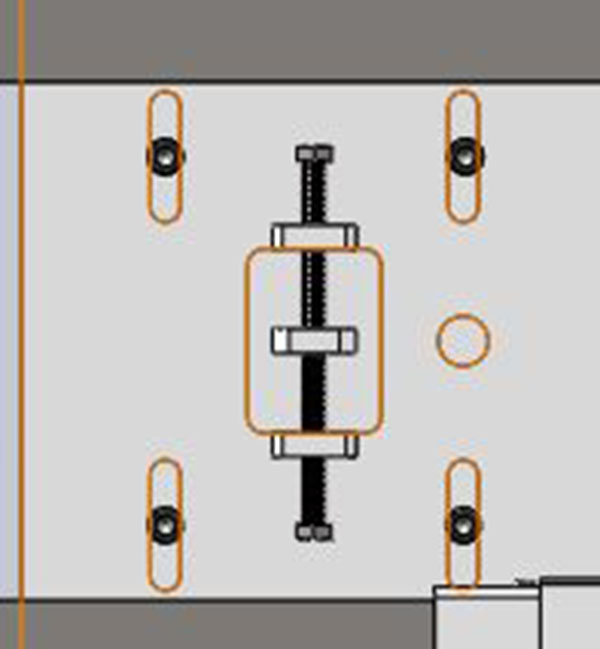
Figure 13
Now Diagonal size adjustment is complete!
Post time: Mar-07-2022